Oscilloscope Probes: Understand and Optimize
Editor’s Note: This article is a guide to predicting the performance of your probe for your specific test setup, including tips on getting the best performance out of your probe.
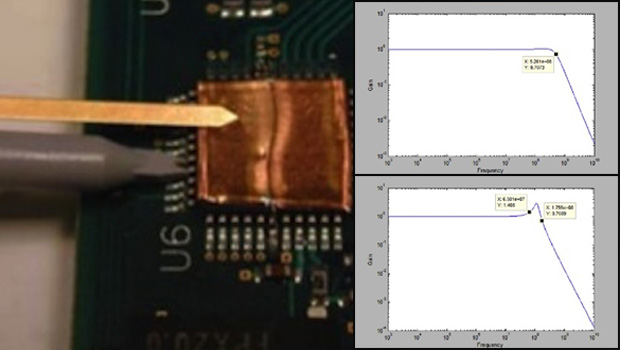
All passive probes have some bandwidth specification that is generally in the range of a few hundred megahertz up to one gigahertz. This bandwidth is measured at the factory using a specialized test jig with a very specific ground inductance and source impedance. Depending on your connection scheme in the real world, the response and bandwidth of the probe can differ significantly.
The go-to oscilloscope probe for most engineers is the basic 10:1 passive probe that comes standard with most scopes. The input resistance and capacitance for any passive probe
are readily available from the data sheet. Typical values you will see for a 500 MHz bandwidth probe are C = 9.5 pF and R = 10 Mohm. One specification that is missing from the data sheet is the ground lead inductance. This is because there are a variety of ways in which people choose to ground their scope probes. The most typical way is using a long ground lead with an alligator clip on the end. This might lead to a ground loop inductance larger than 200 nH, which can significantly compromise the performance of the probe. We can create an equivalent circuit model for such a probe as shown below.
Full article by Stephen Mueller, EDN Network


