Oscilloscope Probes Influence Measurements
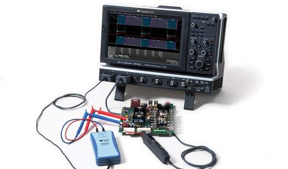
An oscilloscope and a device under test (DUT) constitute a de-facto system. In it, the most overlooked element is the interface between the two: the oscilloscope’s probes. Test personnel simply grab and use probes. Rarely do these engineers consider the probe’s impact on measurements. However, probes are among the most critical elements of the signal chain in any test scenario.
The ideal oscilloscope probe would make contact with the DUT and transmit its signal from the tip of the probe to the instrument’s input with perfect fidelity. It also would exhibit zero attenuation, infinite bandwidth, and linear phase
characteristics at all frequencies. Unfortunately, this probe does not exist in the real world.
The DUT has its particular electrical characteristics for a given signal, which are what we want to measure. However, the probe itself is a circuit with its own electrical characteristics. When the probe tip meets the DUT, the probe suddenly becomes part of a larger circuit, and its characteristics combine with those of
the object of interest in a way that affects the measurement results.
To make a measurement, the probe must “steal” some of the energy present in the DUT and transfer that energy to the oscilloscope’s inputs. For one thing, we introduce the probe’s input impedance into the circuit. To the DUT, the probe constitutes a load presenting resistance, capacitance, and inductance. This load on the circuit can change the signal’s shape and/or the behavior of the DUT.
Full article by David Maliniak, Electronic Design


