
What’s in Your Coaxial Cable?
For almost every application, it is challenging to transfer signals from one component to another while maintaining adequate signal integrity. Adding complex and dynamic signal paths
requires a flexible platform for adapting to many environments and applications. One solution to this problem was proposed by the renowned engineer and mathematician Oliver Heaviside. He patented a design for a shielded telegraph transmission line in 1880.
In 1929, to overcome the limitations in Heaviside’s design, Bell Labs’ Lloyd Espenschied and Herman Affel developed the broadband coaxial cable with an air-like dielectric spacer. Since this invention, coaxial-cable technologies have advanced in both materials and performance, providing solutions for a wide range of RF/microwave/millimeter-wave interconnection problems.
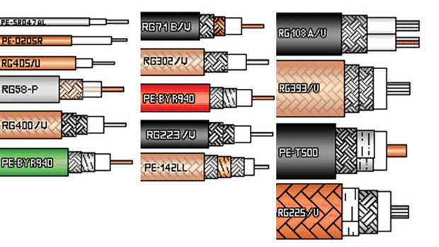
The most basic version of a coaxial cable is composed of a center conductor, which is mechanically separated from a cylindrically symmetric conducting shield by an air-like dielectric. This cylinder-within-a-cylinder conductor geometry allows electromagnetic (EM) signals below a maximum cutoff frequency to create a transverse-electromagnetic (TEM) wave (or an EM wave with perpendicular magnetic and electric components) within the separation space between the conductors.
For signals beyond the cutoff frequency, the size of the wavelengths are small enough to generate non-perpendicular transverse-electric (TE) and transverse-magnetic (TM) waveguide modes. These additional modes reduce signal integrity and performance. Generally, the larger the diameter of the coaxial cable, the lower the cutoff frequency will be. Power-handling capability also increases with size.
Full article by By Jean-Jacques DeLisle, Microwaves and RF
About the Author
Roger Chu is the Marketing Coordinator at GSAmart, the leading GSA sales and marketing partner for technology companies.


